Engineering Information
Spray Angle and Coverage
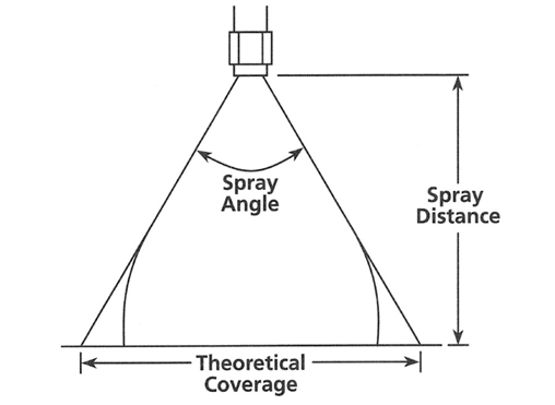
The spray angle does not hold for long spray distances. As illustrated here, the spray angle tends to collapse or diverge as it moves farther from the nozzle orifice.
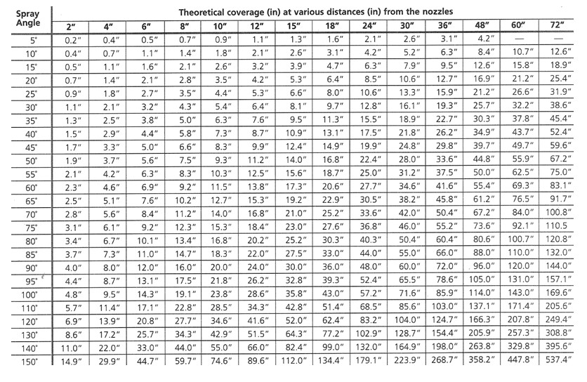
The theoretical coverage of spray patterns at various distances from the nozzle orifice is listed below. These values assume that the spray angle remains constant throughout the entire spray distance. The tabulated spray angles listed are approximate spray coverage using water.
Spray distance varies with spray angle. Liquids are more viscous than water — form smaller spray angles, or solid streams, depending upon nozzle capacity, spray pressure and viscosity. Liquids with surface tensions lower than water produce wider spray angles than those listed for water.
Flow Rate
Defined as the volume of liquid flowing through a nozzle. Steinen flow rate tables for each nozzle type are examples of flow rates at those pressures for water.
Flow rates for pressures not included in the tables may be calculated using the flow rate calculator on each web page.
The formula for calculating flow rates at a given pressure is:
Q2 = Q1 x (Square Root of P2 / P1).
Q1 and P1 are the known flow rate (Q1) and the known pressure (P1). The resulting flow rate (Q2) is calculated for the pressure applied (P2).
Fluid Properties
Fluid pressure has the greatest impact on flow rate, droplet size and spray pattern quality. As liquid pressure to the nozzle increases, the flow rate of the nozzle increases, the spray pattern becomes more uniform, and droplet size is reduced. However, nozzle orifice wear increases with higher pressure as well.
Specific gravity and viscosity of the liquid also effect the flow rate and droplet size. Liquids denser than water have lower flow rates than water at the same pressure. Liquids having high viscosities inhibit water droplets from breaking apart (atomization).
Nozzle Arrangement
Arrangement of Flat Spray Nozzles:
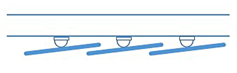
In order to provide uniform spray coverage, the spray widths ought to overlap each other by 1/3 to 1/4. To avoid interferences of the sprays, nozzle orifices should be offset approximately 5°-15° to the pipe centerline.
Example arrangement of Flat Spray nozzles in overlap coverage:
|
|
|
Top View |
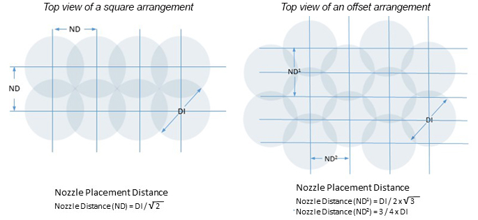
Arrangement of Solid and Hollow Cone Nozzles:
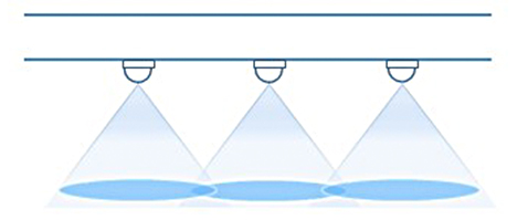
In order to provide uniform spray coverage for Solid Cone and Hollow Cone nozzles, the distance between nozzles should be such that the spray cones overlap each other by 1/3 to 1/4.
Example arrangement of Solid and Hollow Cone Nozzles:
|
|
|
Top view |
Nozzle Problem Troubleshooting
Nozzle flow rates, spray angles, droplet sizes or continuity can be adversely effected by a number of factors:
Wrong Nozzle Used
• Droplet size may be too small or too large
• Spray pattern and/or angle is not correct
• Flow rate may be too high or too low
Nozzle Wear or Corrosion
• Spray patterns becomes irregular
• Droplet size may increase in size
• Flow rate increases to enlarged orifice and/or enlarged internal passageways
Nozzle Clogging
• Reduced flow rates
• Nozzle may exhibit ‘peeing’ instead of spraying
• Nozzle may not spray at all
• The nozzle may have a poor spray pattern
Pipe Size too Small or Piping System Improperly Designed
• Pressure drop through the pipe results in reduced flow rate at nozzle
• Improper piping system design (dead legs) can result in reduced flow rate at nozzle
Poor Nozzle Placement
• Spray fails to properly contact intended target
• Poor spray area coverage
Droplet Size
Nozzle sprays produce a range of droplet sizes from the liquid. Droplet size, typically stated in microns (1 micron = 1/1,000 millimeter or 0.00003937 inches), is usually expressed by a Sauter mean diameter.